X

Author Archives: Evaporated Coatings

  1. A Brief Guide to Thin-Film Optical Filters

    Leave a Comment

    What Are Thin-Film Optical Filters?

    Thin-film optical filters are optical devices consisting of alternating thin layers of specialized optical coatings deposited onto a substrate (e.g., optical glass). The coating layers alter the refractive index of the substrate, changing the direction of the various wavelengths in incoming light as it passes through one layer to the next. Either reflection, transmission, or absorption can occur depending on the wavelength(s) of the incoming light and the type of optical filter employed.

    Types of Thin-Film Optical Filters

    Thin-film optical filters are suitable for use with light in the ultraviolet (UV) to infrared (IR) wavelength range. They can be classified into five basic categories based on their spectral shape: bandpass filters, notch filters, shortpass edge filters, longpass edge filters, and dichroic filters. For more information on the various types available, check out this thin-film optical filter blog post.

    Applications of Thin-Film Optical Filters

    Thin-film optical filters are highly customizable, which allows them to be designed and built for effective performance in extremely specific or unique light-based applications. They are used across a wide range of industries in a variety of devices, equipment, and systems for many different use cases, including, but not limited to, the following:

    • Biological image detection. They can filter luminescence to facilitate the operation of biological imaging devices.
    • Chemical analysis. They can isolate specific emission or absorption ranges from incoming light to aid in chemical identification and analysis operations.
    • Contrast enhancement. They can increase the contrast between objects during scanning and other imaging operations to improve identification, recognition, and verification.
    • Laser systems. They can manipulate the beam of light generated in laser systems.
    • They can separate and modify signal transmissions in telecommunication systems.
    • Visible light coloring. They can add or enhance the hue of visible light to achieve a specific aesthetic effect.

    Thin-Film Optical Filter Solutions From Evaporated Coatings, Inc.

    Thin-film optical filters find use in a variety of light transmission, blocking, and absorption applications. As their design and construction—i.e., the optical substrate and coating used—vary depending the application, some customers may find it challenging to select and source a product that meets their needs. Fortunately, the experts at Evaporated Coatings are here to help.

    At Evaporated Coatings, Inc., we specialize in the supply of high-precision optical coatings. Equipped with over 60 years of industry experience, we can help customers select the right coating and apply it to their substrates. Visit our custom optical filter page to learn more about our thin-film coating capabilities. If you want to discuss your optical filter requirements with one of our experts, contact us today.

  2. A Brief Guide to Beamsplitters

    Leave a Comment

    What Is a Beamsplitter?

    Click to expand

    What Is a Beamsplitter?

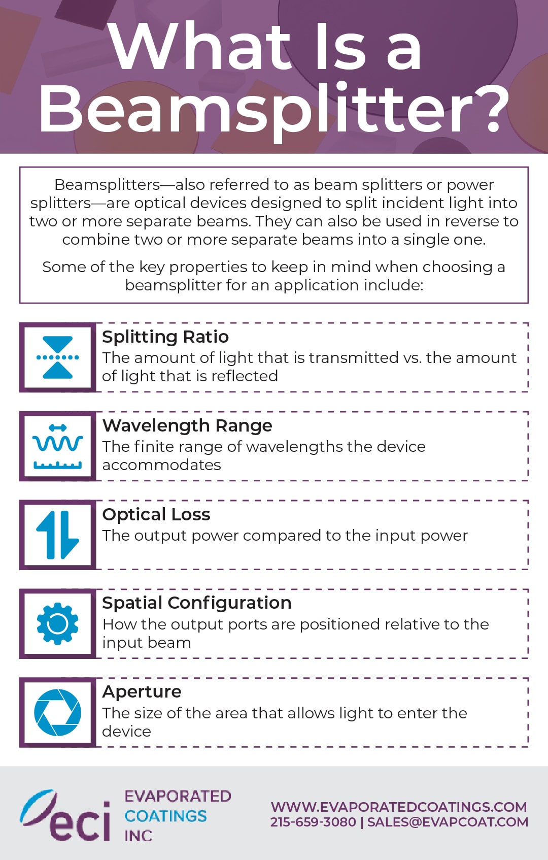
    Beamsplitters—also referred to as beam splitters or power splitters—are optical devices designed to split incident light into two or more separate beams. They can also be used in reverse to combine two or more separate beams into a single one.

    Some of the key properties to keep in mind when choosing a beamsplitter for an application include:

    • Splitting ratio: the amount of light that is transmitted vs. the amount of light that is reflected
    • Wavelength range: the finite range of wavelengths the device accommodates
    • Optical loss: the output power compared to the input power
    • Spatial configuration: how the output ports are positioned relative to the input beam
    • Aperture: the size of the area that allows light to enter the device

    How Does a Beamsplitter Work?

    As indicated above, beamsplitters are used to split incident light into two or more separate beams. The splitting process is dependent on the wavelength, intensity, or polarity of the incoming light and the design and configuration of the beamsplitter. Regardless of these factors, however, all beamsplitters follow the same basic principles: incoming light is split into two or more beams with one or more continuing forward through the optical component (i.e., transmitted) and one or more directed at an angle out of the optical component (i.e., reflected).

    Due to their ability to split light into separate beams based on controlled reflected/transmitted (R/T) ratios, beamsplitters find use in a wide range of light-based devices and equipment, including, but not limited to, the following:

    • Cameras and projectors
    • Fiberoptic systems
    • Head-up displays (HUDs)
    • Laser alignment and attenuation systems
    • Medical imaging systems
    • Sensors

    Types of Beamsplitters

    While all beamsplitters perform the same basic function—i.e., splitting light into separate beams—how they do so varies depending on their design. For example:

    • Standard beamsplitters split incident light without regard to the wavelength, polarization state, or intensity. They are generally used for one-way mirrors and illuminating assemblies and subassemblies.
    • Dichroic beamsplitters split incident light by wavelength. They are typically employed as laser beam combiners or broadband hot/cold mirrors.
    • Polarizing beamsplitters split incident light by polarization state. They are ideal for use in photonic instrumentation systems.
    • Non-polarizing beamsplitters split incident light by intensity. They are suitable for applications that utilize polarized light.

    Standard, dichroic, polarizing, and non-polarizing beamsplitters are available in a variety of configurations. Some of the most common include:

    • Cube beamsplitters. Cube beamsplitters consist of two right-angle prisms connected at the hypotenuse with a semi-reflective coating at the point of connection. They are suitable for applications that require simple mounting mechanisms and durable optical components.
    • Plate beamsplitters. Plate beamsplitters are made from flat and thin glass plate with a special coating on the first surface of the substrate. They are typically used for light with a 45-degree angle of incidence and can be built to support multiple incident ratios.
    • Pellicle beamsplitters. Pellicle beamsplitters are made from very thin substrates. This design allows for minimal beam offset.
    • Polka dot beamsplitters. Polka dot beamsplitters feature a pattern of reflecting dots on the glass surface. This design allows for geometrical beam splitting that is not angle-dependent.

    Custom Beamsplitter Coating Solutions From Evaporated Coatings, Inc.

    Beamsplitters serve a critical function in a wide range of light-based applications. Ensuring they operate as intended necessitates verifying the base substrate has the proper mechanical properties and utilizing the right optical coating. If you’re looking for an experienced and knowledgeable supplier for your beamsplitter coating needs, turn to the experts at ECI.

    At Evaporated Coatings, Inc. (ECI), we’ve supplied high-precision optical coatings for over 50 years. This extensive experience allows us to manufacture beamsplitter coatings for a wide range of R/T ratios, wavelength ranges, angles of incidence, polarization states, incident mediums, and temperature sensitivities and apply them to various customer-supplied substrates (e.g., glass, plastic, molded polymer, semiconductor materials, fibers, and fiber optic devices).

    Visit our beamsplitter page to learn more about our beamsplitter coating solutions. To discuss your beamsplitter requirements with one of our experts, contact us today.
  3. Thin-Film Optical Filters: An Overview

    Leave a Comment

    A thin-film optical filter is produced by placing thin layers of substances that contain specialized optical properties in an alternating fashion on top of a membrane; glass that made specifically for optical purposes, for example. As light passes through an optical filter, its wavelengths change directions as they pass through each layer of the filter. The thin-film coating alters the refractive indices, which results in internal interference, a process that helps to minimize interference from internal reflections. The wavelengths of light can pass through, absorbed, or reflect off of the filter. The kind of optical filter and the wavelength will determine how the light reacts to the filter.

    There are different types of optical filters. Some can transmit light, while others can reflect it, and still others can block it completely. All types can process any wavelength, from the UV range to the IR range. Generally, optical filters are categorized into five key groups according to the spectral shape of the filter.

    1. Bandpass filters. These optical filters transmit a variety of wavelengths while also blocking out the neighboring light.
    2. Notch filters. Notch optical filters block out a range of wavelengths while transferring the light on both sides.
    3. Shortpass edge filters. Optical filters that belong to this category transmit short wavelengths of light and block out longer ones.
    4. Longpass edge filters. Short wavelengths of light are blocked by longpass edge filters, while longer wavelengths are transmitted through them.
    5. Dichroic filters. Certain kinds of wavelengths are reflected by dichroic filters, while other ranges pass through them.

    Typically, edge, bandpass, and notch optical filters work at small angles of incidence (AOI), such as 0 degrees. Dichroic filters, however, are designed to work at an AOI of 45 degrees or larger and are designed in edge, bandpass, or notch arrangements.

    Multiband configurations of optical filters can also be made. Multiband optical filters are bandpass that allow multiple passband. These filters contain several blocking regions and they diffuse all neighboring wavelengths of light. Polychroic filters, for example, are dichroic filters that contain several notches or bands.

    While the majority of optical filters are grouped into the above mentioned categories, customized filters can be made. Custom filters can have any type of spectral shape you can think of; for instance, light waves from a xenon lamp can be made to resemble the spectrum of light the sun produces when passed through a customized filter. Other types of specially made optical filters can correspond with random spectral shapes.

    Since optical filters are so versatile, they can be used in a variety of ways, including:

    If you’re looking for any type of optical filter or coating then get in contact with Evaporated Coatings, Inc. today!

  4. Thoughts on Selecting the Best Camera Filters

    Leave a Comment

    Selecting the optimal optical filter for your shot improves the contrast in images, reducing the processing times required to extract the relevant data from the image. Achieving the highest possible image contrast is the single-most critical factor when designing a machine-based vision system.

    Your choice of aperture size, illumination level, and the quality of your lens all play a significant role in determining the performance of your system. It’s tempting for designers to enhance performance by upgrading lenses or lighting units. However, these additions can add considerably to your costs.

    Fortunately, there’s a way to enhance your system performance and image quality through a more affordable option. Filters offer you the opportunity to improve your image, provided you carefully evaluate any spectral components of your target object. Filters improve performance while providing a minimal impact on the other elements of your image design.


    Understanding the Different Types of Filters

    There is a range of filters available for designers. The filters receive more definition according to the structure of the transmission curve.

    • A long-pass filter blocks short wavelengths while allowing long wavelengths to pass through.
    • A short pass filter works oppositely, blocking longer wavelengths while allowing shorter ones to pass through.
    • A band pass filter transmits central wavelengths, blocking both shorter and longer wavelengths.
    • A notch filter is the opposite of a bandpass filter, passing the shorter and longer wavelengths while blocking the wavelength band.

    Within each of these filter groups, types of filters available depending on the technology solutions used in its creation. For instance, the colored glass filter is unavailable in notch varieties.

    Designers have a vast array of filters available for use on projects. Some of the more common filters include the following.

    The use of a colored glass filter is an affordable and pragmatic solution for enhancing the contrast in applications. However, this practice has limitations on images where broad spectral characteristics distinguish objects, such as in the separation of purple and orange objects.

    An interference filter transmits the specific range of wavelengths, and they offer more precision in use over colored glass filters. An interference filter provides the designer with a nanometer-level control over the transmission of all wavelengths. The same level of accuracy isn’t possible with a colored lens.

    Polarization and neutral density filters may also assist with improving performance in specific imaging situations. Properly incorporating filters into your system requires designers to understand and comprehend the limitations and potential of each of the types of filters available to you.


    Colored Glass Filter

    Spectral discriminations caused by the use of a colored glass filter occurs due to the dopants present in the glass. The concentration and selection of dopants determine the transmission wavelengths and the filter attenuation.

    A colored glass filter offers the designer an affordable solution for many design applications that have relaxed requirements on performance and are angle-independent. The optical transmission never shifts, even with the use of wide-angle lenses, or when tilting on the system’s optical axis.

    It’s important to note that a colored glass filter features a slow transition between the transmission and blocking wavebands, with transmission curves appearing less steep than with using a coated interference filter.

    There are plenty of types of color filters, including a daylight blue filter for balancing colors during the use of color sensors and polychromatic light sources.


    Infrared (IR) Filters

    IR filters are suitable for use in machine vision applications in color and monochrome cameras. Most machine vision cameras feature silicon image sensors that respond to infrared wavelengths. Near-infra-red wavelengths commonly occur due to overhead fluorescent lighting systems, creating inaccuracies in the camera sensors.

    It’s for this reason that most color imaging cameras come with IR-cut filters as standardized equipment mounted over the sensor. Monochrome camera systems will experience massive degradation of the contrast in the image due to the presence of IR light.


    Interference Filters

    For identifying small shifts in color, spectral discrimination of interference filters is a necessity due to the filter’s ability to create sharp transitions between wavelengths they block and transmit. The wavelength-selective interference filter consists of an alternating dielectric layer of low and high refraction indices depositing on a specific surface.

    The uniformity and quality of the surface create a baseline optical quality for the interference filter while defining the wavelength limitations based on the transmission characteristics of the surface.

    Dielectric layering produces detailed spectral characteristics from the filter, creating a destructive interference between the wavelengths that aren’t within the transmission band. As a result, it blocks the wavelengths from transmission through the interference filter.


    Neutral Density Filters

    Gain control over the image brightness without altering the settings for your exposure time of f/#. Both reflecting and absorbing types of neutral density filters can help you lower light transmitted to the sensor in the lens.

    These filters are excellent for use in situations like capturing an image during welding. The neutral density filter reduces the intensity of the light, without compromising any of the other colors or contrast in the image.


    Apodizing filters

    These special filters decrease optical density away from the radial distance of the center of the image. These filters are excellent for handling image hotspots caused by reflections.


    Limitations on Your Filters

    Hard-coated filters get their performance from the specialized coating on the filter, but this same technology also creates limitations on the use of these filters in imagery. Interference characteristics depend primarily on the relationship between the length that light waves travel through a specific medium and the given light of the wavelength.

    When traveling through interference coatings at an unfavorable angle, the light path changes through each layer of the lens, resulting in the modification of the filter’s wavelength selectivity. An interference filter functions and performs based on the distance that the light travels upon the filter.

    With the proper angle of incidence, light waves will incident the filter, and destructively interfere, blocking them from passing through the filter. All interference filters feature a specific Angle Of Incidence (AOI), with most manufacturers setting it at 0°.

    The angular field of view defines the acceptance angle when placing a filter in front of the lens. With a short focal length lens, light transmitted through a filter displays an undesirable effect where the slope decreases due to passband shifts down in the wavelength.

    The common moniker for this effect is “Blue Shift.” For instance, a 4.5mm focal length wide-angle lens has a more significant blue shift than narrow-angled 50mm focal lenses. Designers will find that the filter behaves differently at various field points due to changes in the wavelength ranges: the further out, the more noticeable the blue shift.

    If you’re looking for any type of optical filter or coating then get in contact with Evaporated Coatings, Inc. today!

  5. Coronavirus Update

    Leave a Comment

    Dear Valued Customer –

    We thank you for your loyalty and trust in Evaporated Coatings (ECI) in these uncertain times. We are continuing to monitor the development of the situation around the COVID-19 pandemic. Our goal during this time is to remain to be the high quality and responsive supplier to our valued customer base while emphasizing the need to maintain the health and safety of our employees, customers, suppliers and the community.

    The Governor of Pennsylvania issued an Executive Order dated March 19, 2020, which required the closure of all businesses in the state except those that are “life sustaining” businesses. Business guidance was updated on March 21, 2020 and aligned with the Department of Homeland Security’s Cybersecurity and Infrastructure Security Agency (CISA) to maintain continuity of operations of the federal Critical Infrastructure Sectors.

    As a supplier to many “life sustaining businesses” and companies that are part of the Critical Infrastructure Sector, ECI will continue to remain open and will provide coatings and technical support needed for our customers to effectively conduct operations.

    If your business is continuing to operate under the purview of the federal critical infrastructure sectors, “life sustaining business”, critical government services, or essential construction, please supply ECI with a public letter or a statement of your company’s position on those relevant operations. Send it to sales@evapcoat.com and cc Joe Brychell, VP Sales, jbrychell@evapcoat.com.

    Since the situation continues to changes daily, we invite you to follow ECI on our LinkedIn social network and our website www.evaporatedcoatings.com for further information.

    Thank you for trusting ECI and we look forward to continuing to serve you in the near future.


    Sincerely,

    Kurt E. Stieritz

    President

  6. Filtering in Machine Vision

    Leave a Comment

    Machine vision, also sometime referred to as computer vision, is an extremely important field of computer science that is likely to play a gigantic role in the direction of technology and society moving forward.

    But while many people will focus on the software aspect of machine vision, it is all-too-easy to forget the equally important practical elements that will influence overall performance. One such example is the use of optical coatings and filtering: both of which will either extend or severely limit the possible applications for this highly exciting technology.

    Computer Vision and Optics

    Computer vision/machine vision is the ability of a computer to ‘see’. It does this by using a camera to create a digital image, and then analysing the data that is contained in that image. This is a technology that has been used for a long time, but in the last few years it has been rapidly increasing in importance. That’s because machine learning has enabled rapid improvements in this field, to the point that a computer can not only ‘see’ but also understand precisely what it is seeing: using this information to identify elements in a scene, or even to navigate in 3D space.

    When you think of computer vision, you might think about robotics: specifically, robots that move through a room. This is one application to be sure, but others also include VR, facial recognition, digital assistants, data processing, social media, and much more.

    VR for example uses computer vision in order to understand 3D space, thereby keeping the user safe while they enjoy their immersive experience, while also tracking their virtual movements to their real-world ones.

    In order for all this to work, filtering is needed. These filters are created by doping glass materials with elements that can help to alter the absorption and transmission spectra.

    The precise elements, or ‘dopants’, depend precisely on the wavelength that is desirable for the application.

    The role of these filters is several fold. In some cases, filtering might be used in order to help protect the substrate underneath. For instance, a coating can prevent bright sun from damaging machinery and this could be important for a drone that is being flown in harsh weather conditions.

    Likewise though, filtering can help to provide the first steps in the computational processes that allow machine learning to occur. When navigating through a virtual space for instance, a computer program will only need to look for contrast – which typically denotes an edge. The right filter can help to increase the contrast of the image, thereby making it easier to navigate the scene with less on-board processing necessary.

    Another type of filter might be used in order to provide data not visible to the human eye. For example, an IR light can create a false color on a camera that can degrade the color reproduction and therefore many imaging cameras will use an IR-cut filter for the sensor.

    Conversely, some technologies will use invisible light waves such as IR precisely because they can’t be seen by the human eye. An example is the ‘Leap Motion’ hand tracker.

    Types of Coating

    There are many types of coated filters used in this technology. Typically, coated filters are intended to offer sharper cut on and off transitions and higher transmissions. They are superior in these ways to other colored glass filters.

    Every coated filter will go through a unique manufacturing process that ensures it meets performance targets. Wavelength-selective filters are manufactured using the deposition of dielectric layers added to the substrate. These have high and low refraction indices respectively and can combine to produce a range of desired results.

    Surface quality and uniformity are extremely important factors when choosing the substrate as this can drastically impact on the performance and longevity of the coating.

    There are a wide range of different types of filters, which include bandpass, longpass, shortpass, and notch filters. These each have specific blocking ranges. The explanation is in the name in each case, where the ‘long pass’ filter allows the longest wavelengths to pass through, blocking the shorter wavelengths. Short pass will block longer wavelengths and allow the shorter wavelengths to pass through. Bandpass filters block both longer and shorter wavelengths while only allowing a selected wavelength band in the middle to pass through. Notch filters will only allow wavelengths at either end of the spectrum to pass through while only blocking a selected wavelength band in the middle. Think of this as being like a cut-out or ‘notch’ in the middle of the signal.

    Challenges

    Using these coated filters on cameras and other technologies is a relatively straightforward process, but the unique application of machine vision can introduce some unique difficulties. For example, these filters are designed for a specific Angle of Incidence (AOI) which is normally 0 degrees. This means that only light hitting the lens head-on will be blocked at the right wavelengths. This issue is particularly pronounced with the use of wider angle lenses – as is common in machine vision. Solutions can be applied however, such as moving the lens itself, or having multiple layers of glass. Alternatively, multiple lenses may be used rather than one larger one. Software correction can also help to reduce the noise.

    Even with that limitation in mind however, coated filters will offer superior performance in most cases and is almost always preferred.

    As with all things though, it is important to consider the precise application and other goals of the project. There are huge varieties of different types of machine vision, and using the right filter will depend on the environment, the goals, and the type of image analysis.

    If you’re in need of any type of coating or filter contact Evaporated Coatings!

  7. Fluorophores and Optical Filters in Microscopy

    Leave a Comment

    We humans only have aspect to certain visual information when performing our jobs and making decisions. This might cause us to overlook the huge realms of possible experience available to us then, or the huge amount of data that is constantly available. Fortunately, this is something that technology does take full advantage of – whether it’s computer vision applications that rely on a combination of IR and visible light, or whether it’s fluorescence microscopy.

    In each of these scenarios, the use of effective filters can drastically increase performance by helping machines to ‘see’ the most useful ranges of the electromagnetic spectrum. Below, we’ll take a look at how this crucial technology is saving lives in the field of fluorescence microscopy.

    About Fluorescence Microscopy

    In fluorescence microscopy, a type of fluorescent dye is applied which will then mark particular proteins, tissues, and cells with a ‘fluorescent label’. In other words, these become more visible under the microscope, making it very quick and easy to identify them and separate them out from other types of tissue.

    Fluorophores work specifically by absorbing a particular wavelength – the ‘excitation range’ – and then re-emitting that light back, usually in a different wavelength. This is referred to as the ‘emission range’.

    When you consider the way that humans see colors, it is because a specific wavelength of light is absorbed and only the remainder is reflected back. In this case, the energy is stored and then emitted in a different “format” that we can predict and observe.

    There are many different uses for this kind of technology, from identifying cancerous tissues, to looking at systems such as the vascular system, to following the lifecycle of a medicine in pharmacokinetics.

    Usually, the fluorophore will be excited by higher frequency illuminations – those being UV and violet lights. They will then emit the energy back at a somewhat lower frequency, which will normally be green, or NIR. The specific regions will depend on the precise type of fluorophore being used. The most efficient range of any fluorophore is the ‘peak excitation’ and ‘peak emission’ range.

    As explained, this essentially allows a researcher or medical professional to better see specific types of material and tissue inside a human or animal body, or perhaps to better identify specific types of bacterium within a sample. That in turn makes it much easier to quickly identify the relevant information from an image.

    If you have ever looked through a science journal, then likely you will have seen micrographs showing bright colors that indicate the presence of specific important elements. Many regular health checkups used in hospitals now rely on this technology, but it is also important in research, as well as in other activities such as gene doping and more.

    Fluorochromes generally come in four different types: tiny conjucated organic molecules, fluorescent nano crystals, fluorescent proteins, and finally tandem fluorochromes – which utilize more than one type.

    The Role of Optical Filters

    So what is the role of the optical filter in all of this?

    One type of filter used is the excitation filter. This is placed in the illumination path of the fluorescence microscope. In other words, it filters the light that reaches the fluorophore, thereby ensuring that only the peak excitation range is making it through. This means that less light will be reflected back and more will be absorbed by the target – reducing noise and unwanted information.

    The minimum transmission of the filter is what determines the brightness and brilliance of the image, with an acceptable range being 40-85%. Above 85% is considered ideal. The bandwidth should be restricted specifically to the peak excitation range. This type of filter becomes extremely important if the researcher is using more than one dye in order to look at different types of tissue – this way they can cause only one type of fluorophore to respond.

    The emission filter meanwhile is placed in the imaging path. The role of this filter is of course therefore to only allow light from the fluorophore to return, while blocking out the unwanted light.

    This application sees the same acceptable ranges for the minimum transmission and bandwidth. There may be certain applications however where this filter might be removed in order to view the broader context.

    The dichroic filter, also known as the beamsplitter, is a type of filter that is placed in between the excitation and emission filters. This filter is placed at a 45 degree angle with the role of reflecting the excitation signal toward the fluorophore – ensuring that it will be directly stimulated by the light. At the same time, it will also help to transmit the emission signal toward to detector. This works by refracting light with 95% reflection of the bandwidth of the excitation filter and 90% transmission of the bandwidth of the emission filter.

    It’s very important not only to ensure that the right filters are used for the application in hand, but also that the filters be correctly matched in order to work efficiently together.

    It is up to the client to search for the right filters based on the peak excitation and emission wavelengths of their chosen fluorophores. From there, they might ask for further guidance from the product providers.

    Whichever you choose, these filters play a fundamentally important role in the biological sciences and as they improve, so too does the quality and usefulness of the information we can collect.

    If you’re looking for any type of optical filter or coating then get in contact with Evaporated Coatings, Inc. today!

  8. Optical Coatings for Defense Applications

    Leave a Comment

    Optics form a crucial aspect of numerous military applications. These include the likes of vision systems and target designators, as well as a range of vision enhancing tools used by infantry on the ground.

    Maintaining good visibility for these systems is of critical importance, but it is also an engineering challenge. That’s because optics can be subject to a huge variety of conditions, including various ambient temperatures, humidity, abrasive materials, and more. One piece of military hardware might be forced to reach the upper limits of the Earth’s atmosphere (perhaps even leave it), and some might need to be used in desert storms. Another might need to be left out in the rain for days on end.

    The role of thin film coatings is a highly important one to protect these optics while also maintaining optimal visibility – allowing only the most important wavelengths to pass through, while blocking the unuseful ‘noise’. In these applications, failure could mean the loss of lives, so it’s a hugely delicate balance that needs to be navigated with the utmost caution and attention to detail.

    How it Works

    Optical thin film coatings are extremely thin films that can be applied to lenses, monitors, windshields, and other optical elements in order to protect them while also improving visibility. These materials need to be extremely resilient against corrosive elements and harsh conditions, while also being thin enough so as not to obscure vision.

    Most optical thin film coatings will therefore only be a few microns or even a nanometers thick. This allows the use of much stronger materials – such as metals – without becoming opaque.

    But there is more to a successful application than simply selecting the correct material to begin with. Equally important is thinking about the uniformity of the application (it cannot range in thickness), the adhesion (will it stay in place), the sequence, the refraction indices, and more.

    Acceptable levels might vary on all these metrics depending on the application, budget, and more.

    Generally, there are three primary technologies that are used for these applications. They are:

    • Evaporation
    • Sputtering
    • Chemical vapor deposition

    Each attaches the material to the substrate in distinct methods, and can be operated slightly differently depending on the vendor.

    These methods are each very different and thereby evade direct comparison. However, they each have their own strengths and weaknesses, which should be considered by clients before making a selection.

    Requirements

    As mentioned, optical coatings need to meet a number of set requirements in most applications and situations. We can therefore judge the different approaches by looking at their outcomes.

    To focus a little more on these requirements: the first is hardness. Hardness refers to the ability of the coating to resist damage not only to itself but also to the material it has been applied to. The evaporation method provides the softest films, while sputtering and vapor deposition result in much harder surfaces.

    This also has the added benefit of preventing water molecules from entering the film when in areas of high humidity. Moisture absorption can alter the refractive index, which means that choosing a harder coating can also improve the performance.

    Internal film stress: Coatings will show signs of compressive residual stress/tensile stress. The higher the stress, the more durability you can expect from the product. In other words, it will be likely to last longer before a newer coat is needed.

    Once again, evaporation appears to have the worst performance in this regard, resulting in coatings with the least stress. Higher energy methods like deposition result in greater stress. It is worth noting however that there is a point at which high stress is no longer desirable. Too much stress for a very thick coating can potentially result in a catastrophic failure. For these reasons, very thick coatings using less opaque materials might benefit from evaporation more so.

    Surface roughness: As the name suggests, this refers to the feel of the surface. Roughness and ‘bulk scatter characteristics’ can have an impact on various types of application (if a surface needs to slide beneath another surface for instance) and can also have a negative impact on things like the refraction. If a surface is rough, then it is likely to impact the signal to noise ratio.

    Keep in mind too that surface roughness might result in more grime and dirt attaching to substrate. This can then in turn make it more difficult to keep clean and have an indirect effect on the quality of an image.

    Scatter creates stray light, and can make it more difficult to correctly identify targets and other important subjects. Sputtering tends to be the best option for improved optical efficiency and better contrast/lower noise.

    Choosing a Solution

    When making a solution, it is very important to weigh up these different factors while also considering the cost. Clients may conduct a performance cost analysis in order to analyse the potential expense of the product/solution versus its performance. Certain features may be surplus to requirement, meaning that there is no reason to spend additional money in order to achieve results that aren’t needed by the end user.

    A coating specifier’s role is to correctly choose the best solution to meet performance targets, while avoiding driving costs up unnecessarily.

    An example might be when considering narrow and wide optical bandpass filters and edge filters. These are important elements in military applications that have precise specifications that need to be met (the half power point and center wavelength/full-width half-maximum).

    While there is a lot to consider, ultimately the variety of technologies and varying performance provides the versatility and flexibility for clients to find the precise solutions they need.


    Contact Evaporated Coatings, Inc. for all of your coating needs.

  9. IR Bandpass Filters

    Leave a Comment

    IR bandpass filters are those that are used within the infrared region which is usually defined as 0.7 to 1000 um with three distinct sections that include near infrared, mid infrared and far infrared with far infrared having the most range by far. Because objects at normal temperatures emit IR at wavelengths at around 10 um, the use of multilayer interference filters is needed for their detection. The reasons for their use include the existence of several substrate materials which are transparent have a high refractive index and because of how much wider the mid-IR ranges compared to the visible spectrum and since light division by absorption can only be used as a supplement.

    The optical bandpass filter is a filter which controls our light by creating interference effects that are made by the multilayered thin-film coating on the optical substrate such as sapphire, silicone, germanium or quartz. You select the optical substrate that is closest to the optical specifications.

    There are various applications that it these filters are used for which include controlling machines and equipment, measurement and any other objects that need infrared light. This includes infrared gas analysis with the filter mainly used for detecting CO2 as well as CO, HC and 03 gas density and more. It is also used for flame sensors, exhaust gas sensors in organic sensors.

    In addition, it is used in IR water analysis. The filter can detect H2 absorption so that moisture can be measured. It aids in the radiometric thermometers using IR in for infrared thickness analysis which measures film Agnes detecting HC absorption contained in polymers. Finally, it can be used to create order sorting filter for diffraction grating and in order to detect humans such as in the case of an automatic door or security alarm.

    The infrared bandpass filters need to be developed with durability mind so they can provide high transmission and the projection in order to be able to isolate such a narrow’s spectral region. You also want to make sure that they are easy to maintain and will work in harsh environments. They can be used for everything from FLIR applications to environmental monitoring and used extensively throughout a variety of major industries including the biotech industry, biomedical and chemical applications. The purpose is to selectively transmit a very narrow range of wavelengths and block all of the others. Some of the very specific uses for these interference filters include application instrumentation like colorimetry, environmental testing, clinical chemistry, laser line separation, plan put Tom treat, fluorescence and more. These interference filters are able to select specific spectral lines from an arc or gas discharge lamp. Finally, bandpass interference filters are often used in combination with laser diode modules and LEDs.

    Generally, the customer chooses the central wavelength in bandpass filters as well as the cut-off wavelength and the cut-on value when it comes to broadband bandpass filters. Many companies out there also provide customized IR bandpass filters that are custom-made for whatever purpose of the customer needs them for. The customer may also choose different standard fullwidth half maximum values in bandpass filters such as 1.1%, 2%, 4.3%, 80% or 11%. These are just examples. Each of the specifications refers to the value of the central wavelength of the customer selects. In addition, infrared filters in the range from 1.0 um to 20.0 um are largely customized and produced specifically for customer needs. Some companies provide these in stock, but with many you have to do a special order and have it customized.

    There are lots things that you want to look for when it comes to bandpass filters, but because needs vary so much between one customer in another depending upon the industry that they are going to be using it for and the specific application, it can be difficult to come up with a list of one-size-fits-all factors that you will want to weigh before purchasing. Instead, look for companies that produce the highest quality bandpass filters available and are willing to create just about any customization that you need. Good companies out there will always be willing to do major customizations to customer specifications because that’s how this business in particular works.

    If you’re looking for any type of optical filter or coating then get in contact with Evaporated Coatings, Inc. today!

  10. Applications for BandPass Filters

    Leave a Comment

    The following are some typical applications for optical bandpass filters, which can be provided by Evaporated Coatings, Inc.

    Medical Industry:

    • Ophthalmology
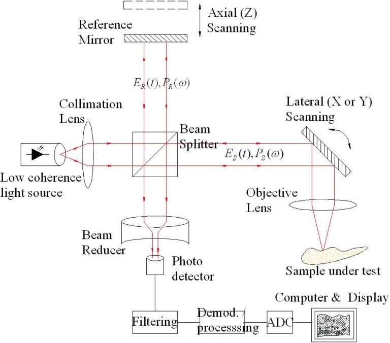
      • Vacuum-assisted laser technology and processes are being employed to develop next generation imaging techniques to reveal structural and functional information from the human retina in a
        non-destructive and non-invasive manner
      • Optical Coherence Tomography (OCT) is a laser-assisted technology for retinal imaging

    Vacuum Assisted Laser technology

    *Adapted from Vacuum Technology & Coating Magazine from February
    2018

    Narrow Band-Pass Filters for Gesture Recognition Systems

    • Distance Measurement Systems
      • Gesture recognition and TOF systems like 3D imaging applications require best transmission performance in the range of the illumination wavelength (Laser or LED source) for a wide field of view. Outside the bandpass an extraordinary blocking is required to suppress the ambient illumination for a better contrast. The filters can be provided in various sizes and if required with B-Stage Epoxy or Solderable coating frames for optional sealing.
    • Multi-purpose cameras for the automotive market
    • 3D imaging applications

    NIR Band-Pass Filters for 800-1100 nm

    • Range finder (golf/hunting)
    • Distance meter for building and construction
    • Automotive sensor systems: Adaptive cruise control (ACC), Lane departure warning (LDW)
    • Industrial safety systems (safety light curtains)
      • Good for environmental stability
      • Enabling superior signal-to-noise-ratio in NIR sensing applications
      • Highly stable spectral characteristics, also under changing environment and temperature
      • Spectral design and flexibility for central wavelength, transmission bandwidth, blocking ranges and levels

    *Adapted from Optic Balzers company website

    From ground to air, explore the types of LiDAR systems

    1. Profiling LiDAR was the first type of Light Detection and Ranging used in the 1980s for single line features such as power lines. Profiling LiDAR sends out an individual pulse in one line. It measures height along a single transect with a fixed Nadir angle.

    2. Small Footprint LiDAR is what we use today. Small-footprint LiDAR scans at about 20 degrees moving backwards and forwards (scan angle). If it goes beyond 20 degrees, the LiDAR instrument may start seeing the sides of trees instead of straight down.

    Two types of LIDAR are topographic and bathymetric:

    i. Topographic LIDAR maps the land typically using near-infrared light.
    ii. Bathymetric LiDAR uses water-penetrating green light to measure seafloor and riverbed elevations.

    3. Large Footprint LiDAR uses full waveforms and averages LiDAR returns in 20m footprints. But it’s very difficult to get terrain from large footprint LiDAR because you get a pulse return based on a larger area which could be sloping. There are generally less applications for large footprint LiDAR. Only SLICER (Scanning Lidar Imager of Canopies by Echo Recovery) and LVIS (Laser Vegetation Imaging Sensor) both built by NASA and are experimental.

    4. Ground-based LiDAR sits on a tripod and scans the hemisphere. Ground-based LiDAR is good for scanning buildings. It’s used in geology, forestry, and heritage preservation and construction applications.

    LiDAR applications professionals use right now

    Light detection and ranging is being used every day in surveying, forestry, urban planning and more. Here are a couple of LiDAR applications that stand out:

    • Riparian ecologists use LiDAR to delineate stream orders. With a LiDAR-derived DEM, tributaries become clear. It’s easier to see where they go far superior to standard aerial photography.
    • Foresters use LiDAR to better understand forest structure and shape of the trees because one light pulse could have multiple returns. As with the case of trees, LiDAR systems can record information starting from the top of the canopy through the canopy all the way to the ground.
    • If Google’s self-driving car got pulled over by the cops, how would it react? Self-driving cars use Light Detection and Ranging. The first secret behind Google’s self-driving car is LiDAR scanner. It detects pedestrians, cyclists’ stop signs and other obstacles.
    • Archaeologists have used LiDAR to find subtle variations in elevation on the ground. It was a bit of a surprise when archaeologists found square patterns on the ground over vegetation. Later, they found these square patterns were ancient buildings and pyramids built by ancient Mayan and Egyptian civilizations.

    Websites and sources regarding GIS:

    https://gisgeography.com/lidar-light-detection-and-ranging/

    http://kustomsignals.com/products/product_category/category/laser

    https://www.eagleview.com/product/pictometry-imagery/specialized-mapping/

Request for Quote ECI will respond to your RFQ online form within 24 hours.